ICL7106 / ICL7107 Pin Settings - Part 2
This IC has an N-Channel FET, which provides a voltage that is 2.8 V below the power supply of the IC. This voltage appears at the COMMON pin 32 and can sink up to 30 mA. It is for battery operation and in cases where the input signal floats with respect to the power supply. The voltage at pin 32 can also be used as a reference; however, there are limitations to this due to internal heating caused by the LED drivers on the ICL7107.
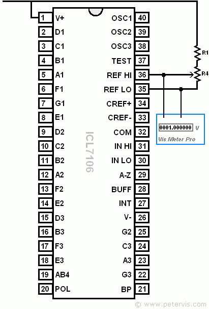
By tying pin 32 to pin 30 (Input Low), we are removing the common mode voltage from the converter. Not connecting these pins would result in the existence of common mode voltage, which the CMRR of the converter would take care of. In addition, tying pin 32 to pin 35 removes the common mode voltage from the reference system. In this design, I am using a 100 kΩ preset between pin 32 and pin 30 as shown in the main schematic. This preset provides facility for zero calibration.
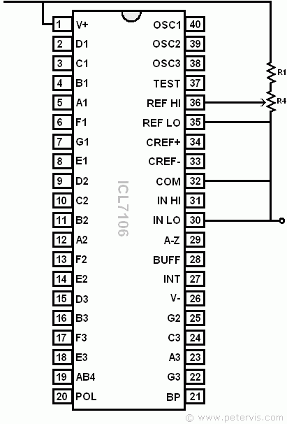
Reference Setting
The voltage between pin 36 (REF HI), and pin 35 (REF LO) should be set to one volt, for a 2 V full-scale mode. This is because at full scale, the ADC generates a value of 2000. The following formula gives a better explanation.
Vin = 2 × Vref
Since Vin is 2 V, Vref has to be 1 V.
In this design, I am using a 1 kΩ preset for R4 and 1.5 kΩ resistor for R1. These values are also recommended in the documentation for a 2 V scale.
This page continues from Part 1.
ICL7106 / ICL7107 Pin Settings - Part 1
ICL7106 / ICL7107 Pin Settings - Part 2
This Article Continues...
ICL7106 / ICL7107 Digital Meter DesignICL7106 / ICL7107 Oscillator Frequency
ICL7106 / ICL7107 Integrate Values
ICL7106 / ICL7107 Pin Settings - Part 1
ICL7107 LED Display Settings
ICL7660 Voltage Converter
ICL7106 and ICL7107 Digital Meter Circuit